

4 points to tell you! New Microwave Wideband Single Pulse Antenna System
2021-05-17
1 Introduction
This paper describes a new type of microwave broadband single-pulse antenna system working in the C~X band, including a sum comparator and a slot antenna array and a broadband power splitter. The research on broadband antennas is relatively early in the world, and there are many types of antennas for implementing broadband antennas, but they are mostly used for phased-array antenna arrays or single-beam antenna arrays, and there are few reports on broadband antennas for single-pulse applications. Domestic research on broadband antennas has not only published many documents but has also been applied to engineering systems. However, the antenna type used more often is a double-arm spiral antenna, and the working system is a wide beam low gain ratio phase single pulse. There are few reports on broadband single-pulse high-gain antenna systems. This paper presents a new type of broadband single-pulse high-gain antenna feeder system.
In this paper, a gradient slot antenna is used as a unit to form an antenna array to obtain a higher gain, and a Lange coupler is used as a basic unit configuration and a difference comparator to form an entire single-pulse antenna feeder system.
2, and poor comparatorThe key component of the monopulse radar is the RF single-pulse processor. This component completes the comparison of the received microwave signals, so it is also called a monopulse comparator or a sum comparator, as shown in FIG. The misalignment and pitch difference signals generated by the sum-difference comparator can be used to determine the target's orientation relative to the radar antenna's viewing angle. In order to overcome the disadvantages of the waveguide structure, planar microstrip structures are used in this paper. A typical waveguide structure with a single-pulse comparison network is designed with a 0°/1803dB coupler, as shown in Figure 2. When four signals are input in phase from the input ports 1, 2, 3, and 4 respectively, the 90 DEG phase difference is generated by the delayer and the 3 dB coupler, so that the four output signals are generated at the corresponding output ports. And difference signal. Port 5 in Fig. 2 is the AND port. Ports 6 and 7 respectively form a pitch difference signal and a position difference signal, and the signal formed by port 8 is an unnecessary signal here. In practice, this port is often added to the matching load. Match the port.
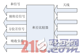
Figure 1 and difference comparator
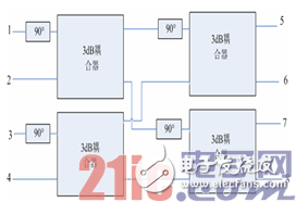
Figure 2. Differential comparator schematic
This paper uses a Lange coupler combined with a 90° delay line to form a single-pulse comparator with a microstrip structure. The HFSS model is shown in Figure 3, ports 1, 2, 3, and 4 are input ports, ports 5, 6, 7, and 8 Is the output port. Using a dielectric substrate with a dielectric constant of 10.2, the line width w of the coupler, distance s between lines, and width w1 of the microstrip feeder were determined by simulation analysis. The denser part of the line in Fig. 3 is a Lange coupler. Its structure is shown in Fig. 4. It belongs to a wideband coupler and has a compact structure. There are 4 ports in total. The input signal is equally divided at the through end and the coupling end. The middle arc The wire is a metal bondwire and is made of fine gold wire.
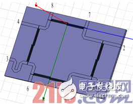
Figure 3: Differential comparator HFSS model
Figure 5 shows the characteristic curve of an input port of a sum comparator, from which it can be clearly seen that the signal input from one input port is approximately equal amplitude output at four output ports, and the return loss and isolation between input ports are The entire frequency band is below -15dB. Other ports are similar and are no longer given.
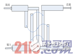
Figure 4, Lange coupler
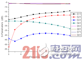
Figure 5, input port characteristics
3, the antenna and antenna array in the systemThe basic unit in the antenna array is an exponentially tapered slot antenna. Figure 6 shows the HFSS model of the tapered slot antenna. The structure of this antenna is relatively simple. It consists of a total of three layers of material: the top layer is a metal ground plate on which a slot structure surrounded by slot lines (solid line) is drawn. The slot line consists of three parts. The first part is a circular slot line cavity, which plays an impedance matching role for the microstrip transmission line; the second part is a rectangular slot line, and the microstrip transmission line plays a role in coupling and transmitting electromagnetic waves; the third part is a gradient slot line, The electromagnetic waves radiated by the antenna play a guiding role. The middle layer is a media board. The bottom layer is a metal microstrip line (shown in red), and the terminal of the microstrip line is a fan-shaped structure, which mainly serves as a terminal load matching, and the microstrip line is coupled and fed to the slot line through the dielectric plate. The standing wave ratio of the antenna mainly depends on the selection of parameters such as the length and width of each matching section of the microstrip feeder, the width of the slot line and the size of the terminal cavity, and furthermore, all the parameters are mutually complementary, and the good radiation characteristics and resident The acquisition of the wave-shaped slot antenna needs to be based on the selection of the antenna's structural parameters. It should be noted that the selection of several parameters of the antenna unit, because the maximum length of the open end can not exceed the high-end wavelength in the operating band, otherwise the array antenna appears at the high end of the grating lobe, the opening can not be too small, because too small low-end radiation characteristics To be affected. The slot antenna is an exponentially changing curve whose equation is:
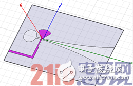
Figure 6. HFSS model of slot antenna
 (1)
(1)
The antenna elements shown in Fig. 6 are composed of four antenna arrays of 2&Times;2, each of which is connected to the input of a difference comparator. Using Rogers 5880 dielectric substrate, substrate thickness 0.508mm, dielectric constant 2.2, terminal opening width 17mm, scale factor R = 0.03, slot line width Wn = 1mm. We use the Wilkinson power divider to form two ports for each input port of the difference comparator in Fig. 3, and connect the two antenna arrays (the antenna array plane is perpendicular to the difference comparator plane). The input ports of the comparators are connected to the 2&Times;2 antenna array to form the entire single-pulse antenna feed system (as shown in Figure 7).
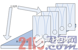
Figure 7. Single pulse antenna array
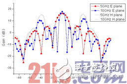
Figure 8. E-plane and H-plane pattern of the antenna
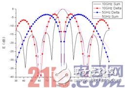
Figure 9: Difference pattern of antenna array
Figure 8 shows the E-plane and H-plane patterns of the high-frequency and low-frequency ends of the antenna array. The E-plane and H-plane patterns of the main lobe match very well. Figure 9 shows the antenna array at the high-frequency end. The low-frequency sum-difference pattern can be seen from the figure, the zero depth of the difference pattern is less than -40dB, and the sidelobes of the pattern are lower than -15dB. After simulation, the gain of the antenna system is in the entire frequency band (5-10GHz). Above 15dB (as shown in Figure 10), the VSWR is less than 2.0 (as shown in Figure 11).
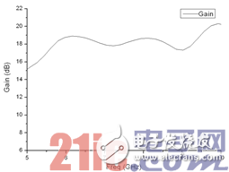
Figure 10, the gain of the antenna array
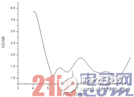
Figure 11. Standing wave ratio of the antenna
4 ConclusionThis paper designs a compact single-pulse antenna feeder system with high gain in C~X frequency band. The gain, beam width, sidelobe level and VSWR of the whole system are all satisfactory.
I-Pulse Feeder, original and new or used one, in stock, high quality.
Material: Stainless steel
Feeder can be divided into tape feeder, tube feeder, tray feeder or stick feeder.
Feeder can be divided into original feeder and replacement feeder.
All the feeders shall be maintained during the use time
In addition, the following spare parts will be sold in our company.
Samsung Feeder
Smt Feeder For Samsung
Panasonic Smt Feeder
Panasonic Feeder
Smt Machine Panasonic Feeder
Smt Feeder For Panasonic
Smt Feeder For Juki
Juki Feeder
Juki Smt Feeder
Smt Machine Juki Feeder
I-pulse Feeder
I-Pulse Feeder, Smt I-Pulse Feeder, Smt Parts I-Pulse Feeder, I-Pulse Type Feeder
Juba Welding Equipments Manufacturing Co., Ltd. http://www.sr-smts.com